RMU 2025 Progress Assessment Criteria
2024-10-21
The Technical Assessment Criteria consist of two parts: robot building specifications display criteria and robot feature display criteria.
The RMOC will first assess teams’ compliance with robot building specifications display criteria. If any mandatory item is not displayed in the video, that type of robot cannot get any points for the feature display part.
It is strictly prohibited to falsify data or engage in dishonest behavior, with the maximum penalty being disqualification.
Regarding the robot feature display content, points will be deducted for any missing or inadequate functions, while additional points may be awarded for unique features beyond the requirements. If mandatory tasks for a robot type are missing, all optional tasks for that robot type will not receive points. It is allowed to film multiple robots under the same robot type, but each robot shown in the filming must complete the mandatory tasks; otherwise, the robot will not receive points. The final score for this robot type will be based on the overall performance of multiple robots.
Before formal filming begins, carefully read the display content requirements and special video display requirements. Strictly adhere to the dimensions and effects specified for display. Any omissions will result in point deductions based on the severity, with the maximum penalty being the deduction of all points for the task.
In the RMUC Techniccal Assessment, after task completion, key data or processes should be displayed as subtitles in the video. Additionally, fill in the data and content required by the assessment template and complete the data report table. Participating teams must fill in truthfully. If there is a discrepancy between the data and the video content, points will be deducted or penalties imposed based on the severity.
It is recommended that participating teams ensure the robot's state closely resembles a combat-ready state, avoiding exposed or disorganized electrical components and cables.
For sped-up videos, the speed multiplier must be clearly indicated.
| Robot Building Specifications Display Criteria | |||
| Event | Robot Type | Display Content | Type |
| RMUC | Infantry/Sentry | The mounting bracket for the UWB Positioning Module and deformation of the bracket when a force of 40 N is applied | Required |
| The mounting area of the Speed Monitor Module (mounted properly in accordance with the Specifications) | Required | ||
| The installation location of the fluorescent energy-charging device (mounted properly in accordance with the Specifications) and self-test according to the Robot Building Specifications Manual V1.1.0. | Required | ||
| Light Indicator Module installation area (correctly installed according to the Specifications) | Required | ||
| The mounting of other Referee System modules or the mounting locations reserved for the Referee System | Required | ||
| Hero | The mounting bracket for the UWB Positioning Module and deformation of the bracket when a force of 40 N is applied | Required | |
| The mounting area of the Speed Monitor Module (mounted properly in accordance with the Specifications) | Required | ||
| Light Indicator Module installation area (correctly installed according to the Specifications) | Required | ||
| The mounting of other Referee System modules or the mounting locations reserved for the Referee System | Required | ||
| Engineer | The mounting bracket for the UWB Positioning Module and deformation of the bracket when a force of 40 N is applied | Required | |
| Light Indicator Module installation area (correctly installed according to the Specifications) | Required | ||
| The mounting of other Referee System modules or the mounting locations reserved for the Referee System | Required | ||
| Drone | The mounting bracket for the UWB Positioning Module and deformation of the bracket when a force of 40 N is applied | Required | |
| The mounting area of the Speed Monitor Module (mounted properly in accordance with the Specifications) | Required | ||
| The installation location of the fluorescent projectile energy-charging device (mounted properly in accordance with the Specifications) and a self-test performed as required | Required | ||
| The mounting of other Referee System modules or the mounting locations reserved for the Referee System | Required | ||
| Dart System | Installation or reserved location for the Referee system. | Required | |
| The orthographic projection of the Dart Launcher and the Darts to be launched on the ground shall not extend beyond the outermost edges of the bottom frame of the Dart System. | Required | ||
| RMUL 3V3 Match | Infantry/Hero/Sentry | The installation area of the Speed Monitor Module (mounted properly in accordance with the Specifications) | Required |
| Light Indicator Module installation area (correctly installed according to the Specifications) | Required | ||
| The mounting of other Referee System modules or the mounting locations reserved for the Referee System | Required | ||
| RMUL Infantry Match | Infantry | The mounting of (or the mounting locations reserved for) the Referee System | Required |
| Light Indicator Module installation area (correctly installed according to the Specifications) | Required | ||
| The installation area of the Speed Monitor Module (mounted properly in accordance with the Specifications) | Required | ||
| RMUL Engineer Challenge | Engineer | Installation or reserved location for the Referee system. | Required |
Robot Function Display Criteria
| Event | Robot Type | Display Content | Special Requirements for Video Display | Requirements in Each Phase | Type | Score |
| RMUC | Full Roster Display | All robots built by the participating team should be shown on full roster; robots can be powered on simultaneously or one after another | Mid-Term & Final Robot Assessment | Required | \ | |
| Infantry | Define a square track with inner dimensions of 5 meters by 5 meters and outer dimensions of 7 meters by 7 meters. At the beginning, the robot should stand still at a random point on the track. Then it moves at a constant maximum speed (as high as possible without exceeding power limits) until it has completed one full lap and finally stops. The chassis power should be limited to 60 W during the process. (If the robot is equipped with a Supercapacitor Module, a full charge of supercapacitors at the beginning is allowed.) | Special
video shooting requirements: Before the feature display begins, use methods
such as displaying the robot's hardware topology to prove that the wiring
complies with robot manufacturing standards and verify the accuracy of the
power recording method. This process can be accelerated but not edited. The
participating team must clearly mark the track boundaries on the ground and
demonstrate the dimensions. Display the power curve graph in real-time. After the robot starts moving, a stopwatch must be displayed throughout the process to show the video is not sped up. At the end of the video, truthfully capture or extract the power recording results during the robot's operation, and show the time taken from the start to the complete stop of the robot. |
Mid-term:
One infantry robot Final: Two infantry robots |
Required | 30 | |
| The robot automatically recognizes and follows a small armor module rotating at a speed greater than 0.4 r/s at a distance of 5 meters, continuously launch 50 projectiles to strike the small armor module. Calculate the hit rate, and display the difference in health or carbon paper marks before and after the target as proof. During the process, the robot can move but must not be touched or interfered with before the project is completed. | Before
the feature display begins, show proof of the distance between the robot and
the target, explain that the target's rotating speed meets the requirements,
display and prove that the robot has emptied the magazine of projectiles,
count 50 projectiles, and load them. The shooter and the target must be
visible within the same frame. Display a stopwatch throughout the process, and the video cannot be sped up. Use the difference in health or carbon paper marks before and after the target as proof of hits. |
Mid-term:
One infantry robot Final: Two infantry robots |
Required | 30 | ||
| Pass smoothly through the launch ramp 3 consecutive times | Display proof of a 17° slope that is 350 mm in height and a landing point further than 650 mm from the top of the slope. The video cannot be edited. | Mid-term:
One infantry robot Final: Two infantry robots |
Optional | 10 | ||
| Climb a 200 mm-high step for 3 consecutive times. | Display proof of the 200 mm step height, with no editing. | Mid-term:
One infantry robot Final: Two infantry robots |
Optional | 10 | ||
| The robot passes through a channel of 550 mm in width and 450 mm in height for 3 consecutive times. | Display proof of the channel width of 550 mm and height of 450 mm, with no editing. | Mid-term:
One infantry robot Final: Two infantry robots |
Optional | 10 | ||
| Display the robot's unique features. Each
feature is worth 2 points, and a maximum of 10 points can be awarded in
total. For example: 1. Simulate activating Small/Large Power Rune: Hit the rotating Small/Large Power Rune with projectiles and count the number of hits on the Power Rune Armor Module each time. Display how the robot moves autonomously to the actual location corresponding to a marked site on the generated map. The robot self-recovers after overturning. |
Relevant dimensions of the site must be demonstrated before the display of each unique feature. Each feature must be performed for at least 3 consecutive times. | Mid-Term & Final Robot Assessment | Optional | 10 | ||
| Hero | Define a square track with inner dimensions of 5 meters by 5 meters and outer dimensions of 7 meters by 7 meters. At the beginning, the robot should stand still at a random point on the track. Then it moves at a constant maximum speed (as high as possible without exceeding power limits) until it has completed one full lap and finally stops. The chassis power should be limited to 70 W during the process. (If the robot is equipped with a Supercapacitor Module, a full charge of supercapacitors at the beginning is allowed.) | Before
the feature display begins, use methods such as displaying the robot's
hardware topology to prove that the wiring complies with robot manufacturing
standards and verify the accuracy of the power recording method. This process
can be accelerated but not edited. The participating team must clearly mark
the track boundaries on the ground and demonstrate the dimensions. Display
the power curve graph in real-time. After the robot starts moving, a stopwatch must be displayed throughout the process to show the video is not sped up. At the end of the video, truthfully capture or extract the power recording results during the robot's operation, and show the time taken from the start to the complete stop of the robot. |
Mid-Term & Final Robot Assessment | Required | 30 | |
| The robot autonomously recognizes and follows a Small Armor Module that is 5 meters away and rotates at a speed of greater than 0.4 r/s, and launch 20 rounds of projectiles continuously to strike the target. Calculate the hit rate and provide relevant evidence. During the process, the robot can move but must not be touched or interfered with before the project is completed. | Before
the feature display begins, display proof of the distance between the robots
and the target, explain that the target's rotating speed meets the
requirements, and demonstrate and prove that the robots have emptied the
magazine of projectiles, counted 20 rounds, and loaded them. The shooter and
the target must be visible within the same frame. Display a stopwatch throughout the process, and the video cannot be sped up. Use the difference in health or carbon paper marks before and after the target as proof of hits. (You can choose to launch multiple rounds, resetting the target's health after each round, and take the sum of hits.) |
Mid-Term & Final Robot Assessment | Required | 30 | ||
| Simulate long-distance strikes on the
Base: 1. At the start, the robot is placed stationary. 2. In the formal stage, the robot first moves a distance of more than 2 meters, then keeps the chassis stationary and launches 10 rounds of projectiles to strike a Large Armor Module or a similarly sized target more than 20 meters away. Note that the target's placement angle and relative ground height should refer to the Base top armor settings in the rule manual. 3. The robot repeats the action in step 2 three times. During the process, the robot moves before launching projectiles, while maintaining a distance of more than 20 meters from the target. 4. The robot’s chassis must stop at three different positions. A total of 30 rounds of projectiles shall be fired. Calculate the hit rate. |
Before
the feature display begins, display proof of the 20-meter distance from the
target and the 2-meter movement. The shooter and the target must be visible within the same frame. After the task ends, display proof of hits. The form of hit rate evidence can be chosen from one of the following three: 1. Difference in target health before and after (can be divided into multiple rounds of launch, resetting target health after each round). 2. Cover the target with carbon paper and observe the marks on the carbon paper. 3. Clear screenshots of the projectile hitting the target taken from a close-up auxiliary camera position (one screenshot per hit). |
Mid-Term & Final Robot Assessment | Optional | 30 | ||
| Display the robot's unique features. Each
feature is worth 2 points, and a maximum of 10 points can be awarded in
total. For example: 1. Smoothly pass over the launch ramp. 2. Ascend a step with a height difference of 150 mm. 3. Display how the robot passes through a channel of 550 mm in width and 450 mm in height. 4. Display how the robot moves autonomously to the actual location corresponding to a marked site on the generated map. 5. Self-recovery after the robot tips over. |
Relevant dimensions of the site must be demonstrated before the display of each unique feature. Each feature must be performed for at least 3 consecutive times. | Mid-Term & Final Robot Assessment | Optional | 10 | ||
| <s> </s> | <s> </s> | <s> </s> | <s> </s> | <s> </s> | ||
| Engineer | Simulate grabbing and exchanging Ores: Initially, the robot is placed more than 2 meters away from the Resource Island. No part of the robot's projection should cross the 2-meter line. After moving, grab the Ores from the Ore Receptacle (inside the Small Resource Island) and exchange them at a location 2 meters away in a straight line from the slot. Display the highest achievable exchange difficulty level, using the Ore Receptacle poses specified in Appendix Table 1: Ore Receptacle's Poses. At least two Ores must be exchanged during the process (exchange time is not limited), with the same difficulty for both exchanges. The Ore Receptacle's location and pose for the two Ores must be different. | Before
the feature display begins, display the size of the corresponding Small
Resource Island and Ores, proving they match the dimensions in the rule
manual. Display and label the size and pose of the Ore Receptacle, indicating
it matches the Ore Receptacle poses specified in Appendix Table 1: Ore
Receptacle's Poses. Specify the location of the Ore barcode and place it
according to the rules. During exchange, the barcode must face the sensing
position of the Ore Receptacle. Throughout the feature display, display a stopwatch. After timing starts, the robot begins to move. The stopwatch cannot be paused in the middle. Mark the time for each complete Ore extraction, the time for completing the Ore exchange, and the total completion time. The video cannot be sped up or edited. |
Mid-Term & Final Robot Assessment | Required | 60 | |
| Complete grabbing of Ores from the Large Resource Island: Refer to the Rules Manual for the placement of Ores on the Large Resource Island, placing 3 Ores in different locations. In the initial state, the robot is placed at a location more than two meters away from the Resource Island, and no part of the robot's projection can cross the 2-meter line. After extracting the Ores, the robot places or transports the Ores to a location beyond the 2-meter line. | Before
the feature display begins, display the size of the corresponding Large
Resource Island and Ores, proving they match the dimensions in the rule
manual. Throughout the demonstration, display a stopwatch. The stopwatch cannot be paused in the middle. Mark the time for each complete Ore extraction and the total completion time. The video cannot be sped up or edited. |
Mid-Term & Final Robot Assessment | Optional | 30 | ||
| Display the robot's unique features. Each
feature is worth 2 points, and a maximum of 10 points can be awarded in
total. For example: 1. Automatic Ore exchange Display how the robot moves autonomously to the actual location corresponding to a marked site on the generated map. The robot self-recovers after overturning. 4. Rescue other robots after they overturn |
Relevant dimensions of the site must be demonstrated before the display of each unique feature. Each feature must be performed for at least 3 consecutive times. | Mid-Term & Final Robot Assessment | Optional | 10 | ||
| Sentry | Define a square track with inner dimensions of 5 meters by 5 meters and outer dimensions of 7 meters by 7 meters. At the beginning, the robot should stand still at a random point on the track. Then it moves at a constant maximum speed (as high as possible without exceeding power limits) until it has completed one full lap and finally stops. The chassis power should be limited to 100 W during the process. (If the robot is equipped with a Supercapacitor Module, a full charge of supercapacitors at the beginning is allowed.) | Special
video shooting requirements: Before the feature display begins, use methods
such as displaying the robot's hardware topology to prove that the wiring
complies with robot manufacturing standards and verify the accuracy of the
power recording method. This process can be accelerated but not edited. The
participating team must clearly mark the track boundaries on the ground and
demonstrate the dimensions. Display the power curve graph in real-time. After the robot starts moving, a stopwatch must be displayed throughout the process to show the video is not sped up. At the end of the video, truthfully capture or extract the power recording results during the robot's operation, and show the time taken from the start to the complete stop of the robot. |
Mid-Term & Final Robot Assessment | Required | 10 | |
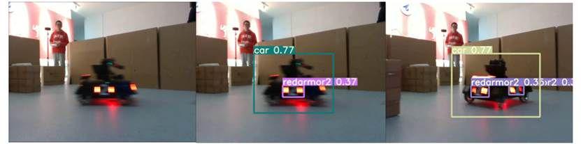
| The robot automatically recognizes and follows a small armor module rotating at a speed greater than 0.4 r/s at a distance of 3 meters (display a stopwatch throughout, video cannot be sped up). The robor continuously launches 50 projectiles to strike the small armor module. Calculate and display the hit rate. Display the visualization program's operation effect for recognizing the small armor module (refer to Figure 1 at the end of the text). The robot can be moved during the process, but it cannot be touched or interfered with before completion. | Before
the feature display begins, show proof of the distance between the robot and
the target, explain that the target's rotating speed meets the requirements,
display and prove that the robot has emptied the magazine of projectiles,
count 50 projectiles, and load them. The shooter and the target must be
visible within the same frame. Display a stopwatch throughout the process, and the video cannot be sped up. Use the difference in health or carbon paper marks before and after the target as proof of hits. |
Mid-Term & Final Robot Assessment | Required | 15 | ||
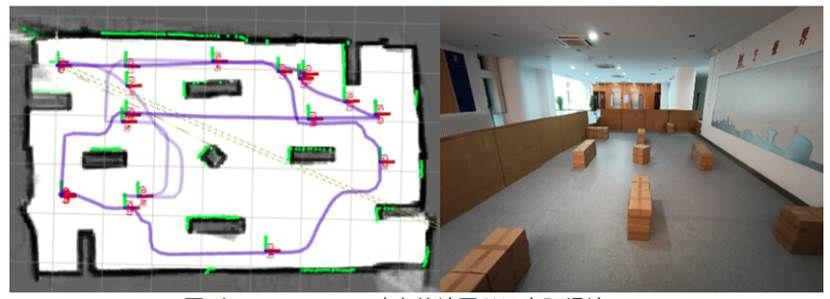
| Display the automatic movement, positioning, obstacle avoidance, and path planning of Sentry at the site and how well the visualization program works, while ensuring that the program running data matches the actual movements of the robot (see Figure 2 at the end of the article). | Mid-Term & Final Robot Assessment | Optional | 10 | |||
| Simulate Sentry navigation and attack: 1. Preparation: Define two points, A and B, which are 5 meters from each other in a straight line. Place an obstacle between A and B that completely blocks the Sentry’s orthographic projection, and set a Small Armor Module or a similarly sized target near point B that rotates at a speed of greater than 0.4 r/s. 2. Function display: The Sentry navigates from point A to B, and the program running data matches the actual movements of the robot (see the task above). 3. The robot automatically recognizes and shoots 50 projectiles at the rotating armor module at point B. Display the visualization program's operation effect for recognizing the armor module (refer to Figure 1 at the end of the text). Calculate the hit rate and display the difference in health or carbon paper marks before and after the target as proof. 4. A maximum of 5 points will be awarded for completing steps 1 and 2, and a maximum of 10 points for completing steps 1, 2, and 3. |
Display
proof of the robot-target distance. Display the robot’s planned path before
its movement. The shooter and the target must be visible within the same
frame. A stopwatch must be displayed throughout the process, and the video must not be sped up. |
Mid-Term & Final Robot Assessment | Optional | 10 | ||
| Display the robot's unique features. Each
feature is worth 1 point, and a maximum of 5 points can be awarded in total.
For example: 1. Smoothly pass over the launch ramp. 2. Display how the robot identifies and pursues the opponent's robots 3. Display how the robot autonomously navigates to and occupies the Fortress Buff Point. |
Relevant dimensions of the site must be demonstrated before the display of each unique feature. Each feature must be performed for at least 3 consecutive times. | Mid-Term & Final Robot Assessment | Optional | 5 | ||
| Drone | 1.
During the preparation stage, display the Drone with full coverage Propeller
Guard, weigh the robot, and present the robot's weight in the video (weight
without loaded projectiles and Referee System. If the Referee System is
loaded during weighing, this weight must be subtracted in calculations). Load
projectiles according to the rules (or load equivalent projectile weight +
analyze the robot's projectile capacity). Specify the position of a Landing
Pad on the ground or another suitable location based on the size of the
site. 2. After takeoff, the Drone flies forward 5 meters and hovers. (A fully enclosed propeller guard must be mounted on the Drone. If the Drone takes off without such a propeller guard, the team will receive zero points for this task and 10 points will be deducted from its overall score. 3. Land back at the Landing Pad. |
Before loading projectiles, verify their quantity by splitting the projectiles into groups with the same number of projectiles or weighing. You can also use equivalent weight and equivalent volume to demonstrate the projectile load for the robots' takeoff. Before the function display begins, the location of the landing pad must be specified, and proof of movement length must be shown. | Mid-Term & Final Robot Assessment | Required | 20 | |
| 1. During the preparation stage, display the
Drone with full coverage Propeller Guard, and mark the Landing Pad Location
on the ground or other locations according to the size of the Competition
Area. 2. After takeoff, the Drone flies forward 5 meters and hovers. (A fully enclosed propeller guard must be mounted on the Drone. If the Drone takes off without such a propeller guard, the team will receive zero points for this task and 10 points will be deducted from its overall score. 3. Continuously launch 50 projectiles, attacking the large armor module from a distance of more than 5 meters. 4. Finally, land at the Landing Pad. |
Before
the function display begins, show proof of the distance between the robots
and the target, demonstrate and verify that the robots have emptied the
magazine of projectiles, count 50 projectiles, and load them. The shooter and
the target must be visible within the same frame. The location of the landing
pad must be specified, and proof of movement length must be shown. Display a stopwatch throughout the process, and the video cannot be sped up. Use the difference in health or carbon paper marks before and after the target as proof of hits. |
Mid-Term & Final Robot Assessment | Required | 30 | ||
| Dart System | Simulate striking the Outpost: Launch 8 darts (4 darts per round, 2 consecutive rounds in total) continuously to attack a Small Armor Module or a similarly sized target 16 meters away. Calculate the hit rate and provide relevant evidence. Note that the target placement angle and relative ground height should refer to the Outpost Dart Detection Target settings in the rule manual. | Display
the on-site transport and deployment of the Dart System in the video. The
commissioning time must not exceed 3 minutes. Display proof of distance from
the target. The Dart System and the target must be within the same frame. Display the stopwatch throughout. After the task ends, display proof of hits. The form of hit rate evidence can be chosen from one of the following three: 1. Difference in target health before and after (can be divided into multiple rounds of launch, resetting target health after each round). 2. Cover the target with carbon paper and observe the marks on the carbon paper. 3. Clear screenshots of the projectile hitting the target taken from a close-up auxiliary camera position (one screenshot per hit). |
Mid-Term & Final Robot Assessment | Optional | 15 | |
| Simulate striking a Random Fixed Target at the Base (8 consecutive shots). Pay attention to the target placement angle and relative ground height, which should refer to the base dart detection target settings in the rule manual. | Display
the on-site transport and deployment of the Dart System in the video. The
commissioning time must not exceed 3 minutes. Display proof of distance from
the target. The Dart System and the target must be within the same frame. Display the stopwatch throughout. After the task ends, display proof of hits. The form of hit rate evidence can be chosen from one of the following three: 1. Difference in target health before and after (can be divided into multiple rounds of launch, resetting target health after each round). 2. Cover the target with carbon paper and observe the marks on the carbon paper. 3. Clear screenshots of the projectile hitting the target taken from a close-up auxiliary camera position (one screenshot per hit). |
Mid-Term & Final Robot Assessment | Optional | 16 | ||
| Display the robot's unique features. Each
feature is worth 2 points, and a maximum of 4 points can be awarded in total.
For example: 1. Simulate striking a Random Fixed Target at the Base (8 consecutive shots). 2. Simulate striking a Random Moving Target at the Base (8 consecutive shots). |
Display
the on-site transport and deployment of the Dart System in the video. The
commissioning time must not exceed 3 minutes. Display proof of distance from
the target. Display the stopwatch throughout. After the task ends, display proof of hits. The form of hit rate evidence can be chosen from one of the following three: 1. Difference in target health before and after (can be divided into multiple rounds of launch, resetting target health after each round). 2. Cover the target with carbon paper and observe the marks on the carbon paper. 3. Clear screenshots of the projectile hitting the target taken from a close-up auxiliary camera position (one screenshot per hit). |
Mid-Term & Final Robot Assessment | Optional | 4 | ||
| Radar | Function normally and display commissioning images | Mid-Term & Final Robot Assessment | Optional | 10 |
| RMUL 3v3 Match | Full Roster Display | Display the full roster of robots made by the team, video shoot of the robots together, with the option to power on simultaneously or one by one. | Required | \ | ||
| Infantry | Complete movement: moving horizontally, rotation. | Required | 10 | |||
| The robot launches 50 rounds of projectiles continuously to strike a target with the size of a Large Armor Module 5 meters away. Calculate the hit rate and provide relevant evidence. | Required | 30 | ||||
| Climb a 15° slope and display power data in real-time. | Optional | 10 | ||||
| The robot automatically recognizes and follows a translating and a rotating Armor Module, respectively, and launches 30 rounds of projectiles continuously to strike the Armor Module. Calculate the hit rates and provide relevant evidence. | Optional | 5 | ||||
| Hero | Complete movement: moving horizontally, rotation. | Required | 10 | |||
| The robot launches 10 rounds of 42 mm projectiles continuously to attack a target with the size of a Large Armor Module 5 meters away. Calculate the hit rate and provide relevant evidence. | Required | 30 | ||||
| Climb a 15° slope and display power data in real-time (show evidence related to the 15° slope). | Optional | 10 | ||||
| The robot automatically recognizes and follows a translating and a rotating Armor Module, and launches 30 rounds of projectiles continuously to strike the Armor Module. Calculate the hit rates and provide relevant evidence. | Optional | 5 | ||||
| Sentry | Complete movement: moving horizontally, rotation. | Required | 10 | |||
| The robot launches 50 rounds of projectiles continuously to strike a stationary target with the size of a Large Armor Module 5 meters away. Calculate the hit rate and provide relevant evidence. | Optional | 30 | ||||
| The robot automatically recognizes and follows a translating and a rotating Armor Module, respectively, and launches 30 rounds of projectiles continuously to strike the Armor Module. Calculate and provide proof of the hit rate (such as carbon paper marks); meanwhile, display how well the visualization program for Armor Module recognition works (see Figure 1 at the end of the article). | Optional | 5 | ||||
| Display the automatic movement, positioning, obstacle avoidance, and path planning of Sentry at the site and how well the visualization program works, while ensuring that the program running data matches the actual movements of the robot (see Figure 2 at the end of the article). | Optional | 5 | ||||
| Display different operation modes of the Sentry (such as patrolling between two points, rotating in place, automatic counterattack, etc.). | Optional | 5 |
| RMUL Infantry Match | Infantry | Complete movement: moving horizontally, rotation. | Required | 10 | ||
| Climb a 15° slope and display power data in real-time. | Required | 10 | ||||
| The robot launches 50 rounds of projectiles continuously to attack a target with the size of a Large Armor Module 5 meters away. Calculate the hit rate and provide relevant evidence. | Required | 30 | ||||
| The robot automatically recognizes and follows a translating and a rotating Armor Module, respectively, and launches 30 rounds of projectiles continuously to strike the Armor Module. Calculate the hit rates and provide relevant evidence. | Optional | 5 | ||||
| Others | Display other unique features | Optional | - | |||
| * Extra points will be given based on the displayed content. |
| Engineer Challenge | Engineer | Complete movement: moving horizontally, rotation. | Required | 20 | ||
| Simulate grabbing Ores from the Resource Island, carrying the Ores and moving in a straight line for 2 meters. | Required | 50 | ||||
| Simulate exchanging Ore using the officially designated poses of Ore Receptacles for each difficulty level (display the highest achievable exchange difficulty level). | Optional | 30 |
Appendix Table 1: Ore Receptacle's Pose:
| Difficulty Level | x | y | z | θ | φ | α |
| Level 1 | -240 | -50 | 720 | 0 | 90 | 0 |
| -120 | -50 | 500 | 0 | 90 | 0 | |
| Level 2 | -130 | 235 | 720 | 0 | 60 | -35 |
| -130 | -235 | 720 | 0 | 60 | 35 | |
| Level 3 | -270 | 0 | 725 | 90 | 50 | 40 |
| -270 | 0 | 725 | -90 | 50 | 40 | |
| Level 4 | -270 | -50 | 720 | 120 | 90 | -45 |
| -270 | -50 | 720 | -120 | 90 | -45 |